
How an Electrical System Works

Updated: Apr. 21, 2024
If your home is grid-connected, your electric power comes from far away. Here's how it gets from the generator to your light bulbs and appliances.
It’s been more than 100 years since the first alternating current power station at Niagara Falls came online. Since then, the United States and eventually the world have been transformed by the electric grid. Towers carrying high-voltage wires and power poles that distribute electricity to homes and businesses dominate the landscape in every developed country. Every region has its own power company to maintain and repair the network.
Each home has its own electrical system, however, and when problems happen there, the power company won’t fix them. To know who to call when problems arise, homeowners need to understand where the power company’s responsibility ends and theirs begins— as well as an understanding of how power gets into the home and is distributed through all the circuits.
Electricity is fascinating, but electrical systems can be complicated, and explanations about how they work can get mired in technicalities. This description (through the eyes of a builder, not an electrician) tries to keep things as simple as possible.
On This Page
The Role of the Line Transformer
Solar power generators notwithstanding, the electrical grids in developed countries are largely fed by steam, water or wind-driven turbines. These turbines produce alternating current (AC) — which changes direction 60 times per second (60 Hertz or 60 Hz.) in North America — and feed it through transmission lines supported by giant towers and power poles.
Think of voltage as the force that propels electricity through wires. Voltage has to be very high (in the order of several hundred thousand volts) to enable transmission over long distances efficiently and at the lowest possible cost. This voltage is too high for practical use, so a line transformer has to step down the voltage (decrease it) to a usable value.
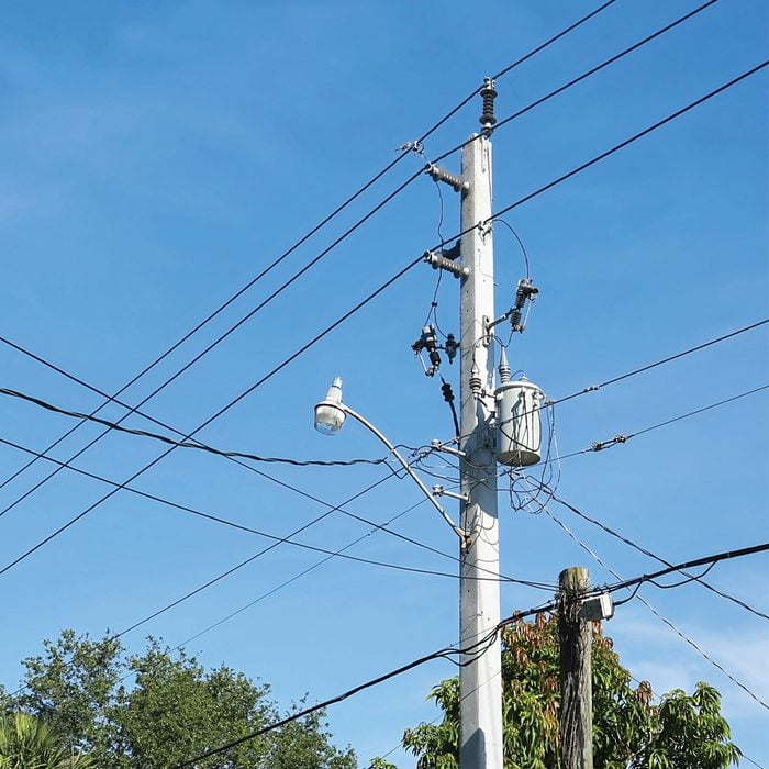
If you look at a power pole, you’ll spot a large metal cylinder at the top. That’s the line transformer, and it steps the voltage down to approximately 120/240 -volts for household use. That’s the standard voltage supplied to one and two-family homes in North America. Other voltage configurations are used for commercial and industrial buildings.
In many areas, says master electrician John Williamson, the local utility distribution system is buried underground, so the utility transformers are in the familiar pad-mounted green boxes you see in some residential neighborhoods.
“The regional power grid operators work tirelessly and silently around the clock to make sure that the voltage and 60-Hz frequency of the grid is stable and consistent,” he says. “This is something we all take for granted.”
From the Transformer to the Meter
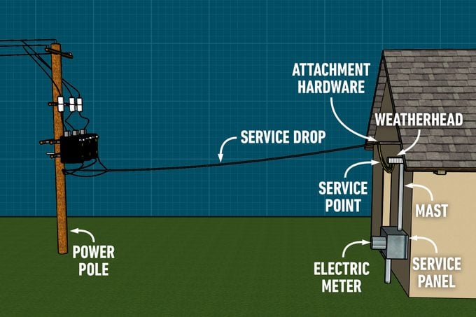
The typical overhead service drop that runs from the transformer to the home carries three wires: two hot wires and one neutral wire. The measured voltage is 240 volts from hot to hot, and 120 volts between the neutral and each hot wire. You find the same basic configuration of three insulated wires in underground installations.
First, they pass through the weather head, which is a length of conduit firmly attached to the roof or siding with a goose-necked opening to keep rain out. Then the next stop for the service-entrance wires is the electric meter, which is usually attached to the side of the house just under the weather head. The wires connect to the meter’s Line terminals, which allows the meter to monitor the flow of current to the house.
Most meters today are smart meters and automatically relay this information to the power company via wireless radio signals. This eliminates the need for utility meter readers to visit every home. The glass watt-hour meter belongs to the power company, but the meter socket enclosure and all components of the premises’ electrical system that come after it belongs to the homeowner.
From the Meter to the Service Panel
From the Load terminals, which are on the opposite side of the meter from the Line terminals, the service-entrance wires then go to the main service panel. Before they get there, they typically have to pass through a wall. At that point, there is usually a junction box or conduit fitting (with a removable cover) attached to the side of the house. They could also pass through an exterior service disconnect switch, which the National Electrical Code (NEC) requires as of 2023 but older houses may not have.
“The NEC now requires an exterior emergency disconnect switch for first responders,” explains Williamson, “but an exterior Service Disconnect can satisfy two code rules at the same time: it serves both as an Emergency Disconnect and the Service Disconnect. Emergency first responders can use the exterior disconnect switch to cut power to the house before entering.”
The main service panel is indoors, usually in the basement, a utility room or a garage. The wires come through the wall and enter through the top or bottom of the panel. Each wire connects to a main circuit breaker and then to copper or alloy bus bars, which are designed to mate with circuit breakers. The circuit breakers simply “plug onto” the panel’s bus bars.
The MAIN breaker, as it is often labeled, can also be used as a main disconnect in homes predating 2023. It is designed to trip open and turn off when the current load exceeds its rating. For new construction, the NEC requires a minimum rating of 100 amps for a dwelling unit, but larger homes may need 200-amp service or more.
Inside the Panel
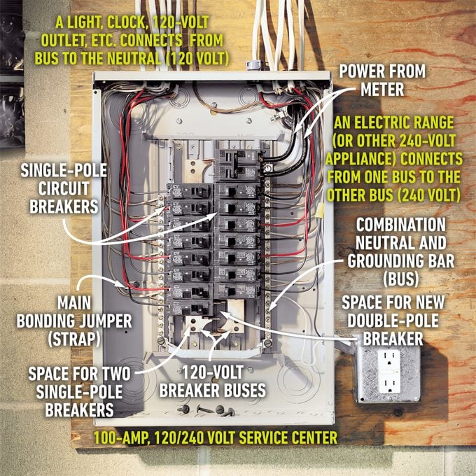
The two copper or alloy bus bars are known as the “hot bus bars”, and the voltage between them is 240 volts. Besides these, there are two other terminal bars, the neutral bar and the equipment grounding bar.
The neutral terminal bar
The neutral terminal bar is usually nickel-plated and has a silver coloration to distinguish it from the copper hot bus bars. The white neutral wires for 120-volt branch circuits terminate on the neutral terminal bar which, in turn, connects to the transformer by a white neutral service-entrance wire. This provides a way for electricity originating from either hot bus to return to the transformer and form a complete circuit.
The equipment grounding bar
Most panels have an extra terminal bar that connects directly to earth (ground), often by means of a ground rod pounded into the ground just outside the home, but the NEC has several options for these “grounding electrodes.” They can connect to the underground municipal metal water service pipes that supply the house or — in new construction — to reinforcing steel in the home’s concrete footings.
All the branch circuit cables in the home have a bare (or green) equipment grounding wire that connects to this terminal bar. The grounding conductor provides a direct low-resistance path for ground-fault current back to the electrical panel, where it blows a fuse or trips a circuit breaker. The grounding conductor runs continuously through the circuit, connecting to every receptacle, light switch and fixture and every metal electrical box.
Circuit Breakers and Branch Circuits
All circuit wires that feed electrical devices in the home, such as lights, receptacles and appliances, originate in the main service panel. Although there are exceptions, circuit cables have a white wire that connects to the neutral bar, a bare or green ground wire that connects to the grounding bar and one or two hot wires (black and/or red), depending on whether the circuit operates at 120 or 240 volts.
Instead of connecting directly to the hot bus, the hot wire for each branch circuit connects to a circuit breaker that trips and cuts power to the circuit when the current draw exceeds its rating. Single-pole breakers that control 120-volt circuits are usually rated for 15 or 20 amps, and each one snaps into a slot that automatically connects it to one of the bus bars. Two-pole breakers for 240-volt circuits have to contact both bus bars.
All the panel wiring is hidden by a door and — behind it — a dead-front cover that screws onto the front of the panel and leaves only the circuit breakers exposed. The metal panel enclosure is designed to contain any accidental arcing or sparking, and it keeps people from sticking their hands and fingers where they don’t belong. Labels or a panel index on the door or cover indicate which circuit in the house each breaker controls.
Originally Published: July 25, 2023